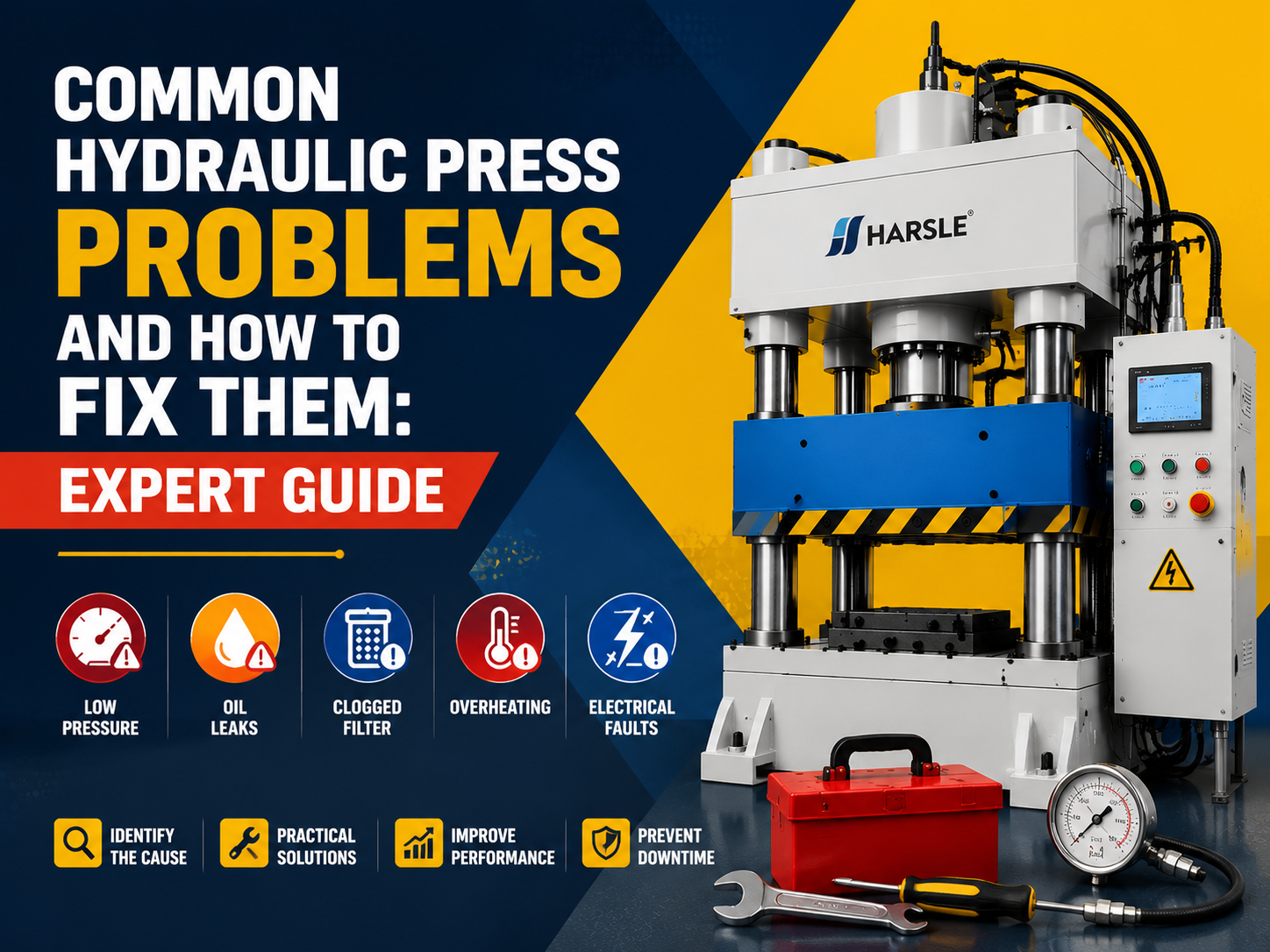
Troubleshooting Why Your Hydraulic Press Stopped Mid-Cycle
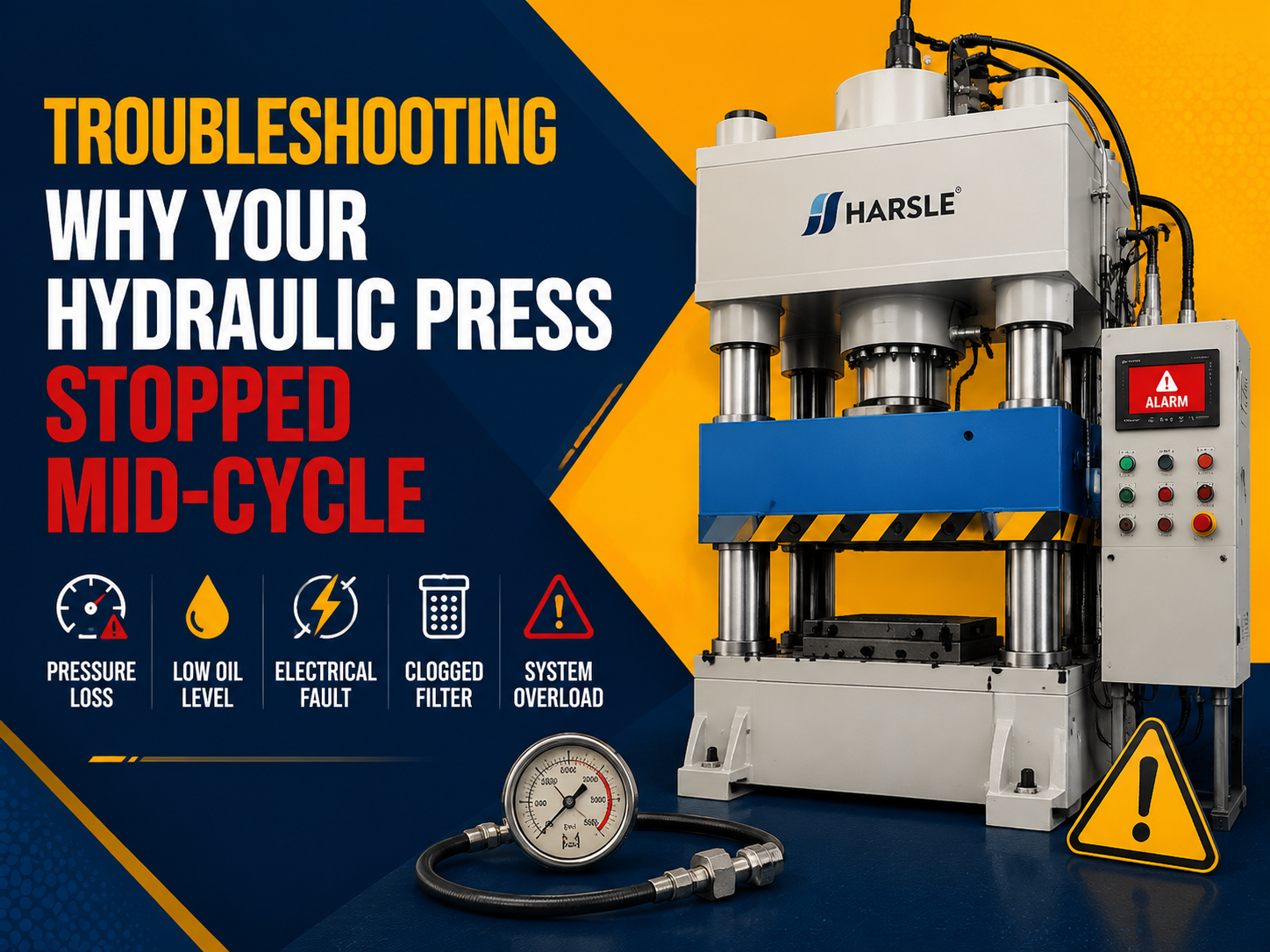
A sudden interruption during a heavy-duty production run is more than just a mechanical failure; it is a significant disruption to the manufacturing workflow that carries high operational costs. When a hydraulic press stopped mid-cycle, the immediate concern for any production manager or mechanical engineer is identifying whether the fault lies within the hydraulic circuit, the electrical control system, or the mechanical structure itself. These machines, essential for deep drawing, stamping, and forging, rely on a delicate balance of fluid dynamics and precision electronics. A stoppage mid-stroke can occur during the rapid advance, the pressing phase, or the return stroke, and each phase points to distinct potential failures. Understanding the nuances of these systems is critical for performing an effective root cause analysis (RCA) and implementing a permanent fix rather than a temporary workaround. This article provides a professional technical framework to diagnose these stoppages, ensuring your sheet metal fabrication equipment returns to peak performance while maintaining safety and precision standards.
Understanding the Basics of Hydraulic Press Operation
To diagnose why a hydraulic press stopped mid-cycle, one must first understand the sequence of operations within a standard industrial hydraulic circuit. Most modern presses operate on the principle of Pascal’s Law, which states that pressure exerted anywhere in a confined incompressible fluid is transmitted equally in all directions throughout the fluid. The cycle typically begins with a signal from the Programmable Logic Controller (PLC) to the directional control valves. These valves direct high-pressure oil from the pump to the piston side of the cylinder, initiating the downward stroke. A mid-cycle stop occurs when the equilibrium of force, flow, or electrical logic is broken. This could be due to a loss of pressure (force), a blockage in flow (speed), or a safety interlock being triggered (logic). Identifying which of these three pillars has failed is the primary goal of the troubleshooting process.
Why This Topic Matters in Sheet Metal Fabrication
In high-volume sheet metal fabrication, consistency is the foundation of quality. When a hydraulic press stops unexpectedly, the consequences extend beyond downtime. First, the workpiece currently being processed is often rendered scrap, especially in deep drawing or precision bending applications where material springback or work-hardening occurs if the pressure is not maintained. Second, a sudden stop can induce hydraulic shock (water hammer) within the piping, potentially leading to catastrophic seal failure or cracked manifolds.
“A hydraulic press that stops mid-cycle is often the system’s way of preventing a more catastrophic mechanical failure; the challenge is determining if the stop was a protective measure or a component collapse.”
Finally, from a safety perspective, a machine that stops mid-cycle may have stored energy in the form of compressed fluid or mechanical tension, posing a significant risk to technicians during the inspection phase.
Key Factors to Consider During Diagnosis
When conducting an RCA on a stoppage, engineers should focus on several critical technical factors. These factors often interact, meaning a failure in one can mask a symptom in another.
- Fluid Contamination: Particles can jam the spool in a directional valve, preventing it from shifting fully and causing the press to stall.
- Thermal Stability: Overheated hydraulic oil loses viscosity, leading to internal leakage and a loss of the pressure required to complete the stroke.
- Electrical Continuity: Limit switches and proximity sensors provide the feedback necessary for the PLC to continue the cycle; a loose wire can mimic a mechanical stall.
- Pump Efficiency: A worn pump may provide enough flow for the low-pressure advance but fail to sustain the high pressure required for the work stroke.
- Relief Valve Settings: If a relief valve is set too low or has a weakened spring, it may bypass oil to the tank before the target tonnage is reached.
Technical Explanation and Calculation of System Pressure
The ability of a hydraulic press to complete its cycle depends on the generation of sufficient force (F) to overcome the resistance of the material being formed. This is expressed by the formula: P = F / A. In this context, P is the system pressure (measured in bar or PSI), F is the required force (tonnage), and A is the effective area of the cylinder piston (in square inches or square centimeters). If a press stops mid-cycle, it is often because P is falling below the requirement. For example, if a 100-ton press (200,000 lbs) has a cylinder with a 10-inch diameter, the piston area is approximately 78.54 square inches. To reach full tonnage, the system pressure must be: P = 200,000 / 78.54 = 2,546 PSI. If a pressure gauge at the pump shows 3,000 PSI but the press stalls, the loss is occurring between the pump and the cylinder, likely through a leaking seal or a malfunctioning valve. Conversely, if the gauge only shows 2,000 PSI, the pump or the relief valve is the primary suspect.
Comparison of Potential Failure Points
Different types of valves and systems have different failure modes. The following table compares common components that cause mid-cycle stoppages.
| Component | Failure Mode | Typical Symptom | Diagnostic Method |
|---|---|---|---|
| Solenoid Valve | Coil Burnout or Spool Jam | Instant stop, no movement in either direction. | Check for magnetic field at the coil or manual override. |
| Proportional Valve | Electronic Drift | Slow down before stopping mid-cycle. | Monitor 4-20mA or 0-10V signal. |
| Main Relief Valve | Spring Fatigue | Stops specifically when load increases. | Test pressure at the test port while under load. |
| Piston Seals | Internal Bypass | Drifts downward or stops when pressure peaks. | Check return line flow during high-pressure hold. |
| PLC Input | Sensor Misalignment | Intermittent stopping at a specific stroke height. | Inspect proximity switch LEDs and bracket rigidity. |
Step-by-Step Guide to Root Cause Analysis
When your hydraulic press stopped mid-cycle, follow this systematic approach to identify the root cause.
- Safety First: Engage the mechanical ram safety blocks and lock out/tag out (LOTO) the electrical power before any physical inspection.
- Visual Inspection: Check for external leaks, blown hoses, or structural damage. Examine the oil level in the reservoir and the condition of the filters.
- Monitor the PLC Status: Look at the PLC input/output (I/O) indicators. If a specific input (like a ‘top of stroke’ or ‘work pressure reached’ sensor) is flickering or off, the machine may think it has reached the end of its cycle prematurely.
- Test the Electrical Components: Use a multimeter to verify voltage at the solenoids. A solenoid may click but fail to shift the spool if there is internal mechanical resistance.
- Analyze Hydraulic Pressure: Install pressure gauges at various points: the pump outlet, before the directional valve, and at the cylinder ports. This allows you to see where the pressure drop is occurring.
- Examine the Valve Spools: If pressure is present but no movement occurs, the spool inside the directional valve may be stuck due to varnish or contamination.
- Perform a Load Test: If the machine runs empty but stops under load, the issue is likely a bypass in the cylinder seals or a failing pump.
Common Mistakes to Avoid
In the rush to resume production, maintenance teams often make critical errors that can lead to further damage. One common mistake is simply turning up the relief valve pressure. If the press stopped mid-cycle because of a mechanical obstruction or a failing seal, increasing the pressure can lead to a catastrophic hose burst or structural cracking. Another frequent error is ignoring the oil temperature. If the press stops only after several hours of operation, the cooling system is likely the culprit, not the valves. Additionally, never bypass safety interlocks or light curtains to “test” a cycle; these systems are often the cause of the stop, but they are performing their intended function of protecting the operator from a perceived hazard.
Industry Applications and Real-World Scenarios
In the automotive sector, large-scale hydraulic presses are used for stamping body panels. A stoppage mid-cycle here is often traced back to the complex synchronization required between the press and the automated transfer system. If the transfer arm is not in the ‘clear’ position, the press PLC will halt the cycle immediately to prevent a collision. In aerospace manufacturing, where exotic alloys are formed at high temperatures, a press might stop because the material resistance exceeded the pre-set tonnage limits due to a drop in the heating furnace temperature. In these cases, the press is functioning correctly, and the root cause lies in the peripheral process equipment.
“Troubleshooting must extend beyond the machine frame; the environment and the material are as much a part of the hydraulic system as the pump itself.”
Conclusion: Maintaining Reliability
A hydraulic press that stops mid-cycle is a complex puzzle that requires a blend of mechanical intuition and technical data. By understanding the relationship between hydraulic pressure, electrical logic, and mechanical resistance, engineers can move beyond guesswork to precision diagnostics. Regular maintenance—specifically oil filtration, seal inspection, and sensor calibration—is the only way to prevent these stoppages before they happen. For long-term reliability, ensure that all operators are trained to recognize the early signs of hydraulic distress, such as increased noise or slower cycle times, which almost always precede a complete mid-cycle failure.
FAQ
Why does my press stop only when it reaches the workpiece?
This usually indicates a pressure-related failure. The system can handle the low-pressure advance but fails when the load increases. Check the main relief valve setting or inspect for internal bypassing in the cylinder seals.
Can air in the hydraulic lines cause a mid-cycle stoppage?
Yes, air is compressible, unlike hydraulic fluid. Significant air ingestion can cause erratic movement or a total loss of pressure, leading the controller to trigger a safety stop due to unexpected ram velocity or position.
How do I know if the solenoid coil is burnt out?
Use a multimeter to check for resistance (ohms) across the coil terminals. An infinite reading indicates an open circuit (burnt coil), while zero resistance indicates a short. You can also check for a magnetic field using a screwdriver while the coil is energized.
What role does the backgauge play in mid-cycle stops?
In many synchronized presses, if the backgauge loses its position or hits a limit, the PLC will halt the press ram to prevent tool damage. Ensure the backgauge homing sequence is completed and sensors are clean.
Is it safe to restart a press that stopped mid-cycle immediately?
No. You must first identify if the stop was caused by a mechanical jam or pressure loss. Restarting without clearing the root cause can cause the ram to drop unexpectedly or damage the hydraulic pump due to cavitation.