Industrial Guide: Troubleshooting Pressure Switch and Sensor Failures

In the high-precision world of sheet metal fabrication, maintaining consistent force and gas flow is paramount. Whether it is the immense hydraulic force required by a press brake to form thick steel plates or the delicate assist gas pressure needed for a fiber laser to achieve a dross-free cut, pressure monitoring components are the unsung heroes of the factory floor. However, when these components fail, the result is often immediate downtime, safety hazards, or scrapped workpieces. Troubleshooting pressure switch and sensor failures requires more than just a basic understanding of electronics; it demands a holistic view of the machine’s hydraulic, pneumatic, and electrical architecture.
Reliable pressure feedback is the primary safeguard between a perfectly formed part and a catastrophic machine overload.
Engineers and maintenance managers must distinguish between the binary nature of a switch and the continuous feedback of a sensor to effectively resolve system faults. This article provides a comprehensive technical framework for troubleshooting pressure switch and sensor failures, specifically tailored for the sheet metal industry where vibration, oil contamination, and electrical noise are constant challenges.
Understanding the Basics: Switches vs. Sensors
Before diving into troubleshooting pressure switch and sensor failures, we must define the two primary technologies used in fabrication machinery. A pressure switch is a mechanical or electronic device that opens or closes an electrical circuit when a specific pressure threshold is reached. It is a binary device, typically used for safety interlocks or simple pump control. In contrast, a pressure sensor (or transducer) provides a continuous electrical signal (such as 4-20mA or 0-10V) proportional to the pressure being measured. This allows the machine’s PLC (Programmable Logic Controller) to monitor real-time fluctuations and adjust parameters dynamically.
Why Troubleshooting Pressure Switch and Sensor Failures Matters
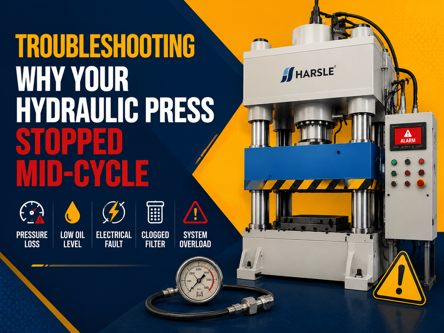
In sheet metal fabrication, pressure regulation directly correlates to quality and safety. For instance, in a hydraulic press brake, an inaccurate pressure sensor can lead to incorrect tonnage calculation. If the sensor fails to report the correct pressure, the machine may over-travel or apply insufficient force, resulting in incorrect bending angles. In pneumatic systems for laser cutting, a failing switch might not detect a drop in nitrogen assist gas, leading to lens contamination or poor cut quality. Timely troubleshooting prevents long-term damage to expensive hydraulic pumps and ensures that safety systems, such as emergency stops triggered by overpressure, remain functional.
Key Factors to Consider During Diagnosis
When approaching troubleshooting pressure switch and sensor failures, several technical factors influence the accuracy of your diagnosis:
- Hysteresis: This is the difference between the set point (where the switch activates) and the reset point (where it deactivates). In mechanical switches, excessive hysteresis can cause system oscillation.
- Repeatability: If a sensor provides different readings for the same pressure input over multiple cycles, internal fatigue or diaphragm damage is likely.
- Media Compatibility: In hydraulic systems, the seal material (e.g., Viton, NBR) must be compatible with the hydraulic fluid. Swollen seals often lead to sluggish response or total failure.
- Electrical Interference (EMI): Industrial environments are rife with noise from VFDs and motors. Improperly shielded cables can induce false pressure spikes in sensor readings.
Technical Explanation: The Role of Pressure in Tonnage Calculation
Troubleshooting pressure switch and sensor failures often involves verifying the sensor’s output against the physical output of the machine. In a hydraulic press brake, the tonnage (Force) is a function of the hydraulic pressure and the surface area of the piston. The formula is expressed as:
F = (P × A) / 1000
Where:
- F = Force or Tonnage (Metric Tons)
- P = Hydraulic Pressure (Bar)
- А = Total Effective Area of the Cylinders (cm²)
If your press brake is rated for 100 tons but is failing to bend material that requires only 80 tons, and the pump is audible, the pressure sensor is likely providing a false ‘high’ reading to the PLC, causing the controller to truncate the stroke prematurely. Verification requires installing a calibrated mechanical master gauge to the manifold to compare ‘Actual Pressure’ vs. ‘Sensor Reported Pressure’.
Comparison of Component Types
The following table compares the two most common types of pressure monitoring devices found in sheet metal equipment:
| Особенность | Mechanical Pressure Switch | Electronic Pressure Sensor |
|---|---|---|
| Output Type | Switch Contact (ON/OFF) | Analog/Digital Signal (Linear) |
| Life Cycle | Lower (Mechanical Wear) | Higher (No Moving Parts) |
| Возможность регулировки | Manual Spring Tension | Software/PLC Configurable |
| Точность | +/- 2% to 5% | +/- 0.1% to 1.0% |
| Typical Use | Safety Overpressure, Oil Filters | Tonnage Control, Gas Regulation |
Step-by-Step Guide to Troubleshooting Failures
Follow this systematic engineering approach for troubleshooting pressure switch and sensor failures:
- Physical Inspection: Check for external leaks around the thread (NPT/G). Verify that the electrical connector (M12 or DIN) is seated correctly and free of oil or moisture.
- Power Verification: Use a multimeter to ensure the sensor is receiving the correct excitation voltage (typically 24V DC in modern CNC machines).
- Signal Isolation: For sensors, measure the output loop. If using a 4-20mA signal, a reading of 0mA usually indicates a broken wire, while a 4mA reading indicates 0 pressure. Anything outside the 4-20mA range suggests internal electronics failure.
- Mechanical Verification: Install a manual ‘master’ gauge in parallel with the sensor. Compare the readings. If the manual gauge shows 200 bar but the CNC display shows 150 bar, the sensor requires calibration or replacement.
- Test the Switch Continuity: For mechanical switches, use the continuity setting on your multimeter. Manually actuate the system to the setpoint and observe if the contacts flip state.
Common Mistakes to Avoid
During the process of troubleshooting pressure switch and sensor failures, technicians often make these critical errors:
- Ignoring Dampening: High-pressure hydraulic systems experience ‘spikes.’ Failure to use a snubber or dampener can lead to premature diaphragm rupture in the sensor.
- Incorrect Thread Identification: Forcing a BSPP sensor into an NPT port will destroy the threads and cause high-pressure leaks. Always verify thread standards.
- Over-tightening: Excessive torque can deform the sensing element inside the housing, causing a permanent offset or zero-point drift.
- Confusing NPN and PNP: In electronic switches, using an NPN sensor on a PNP-configured PLC input will result in no signal detection despite the sensor functioning correctly.
Industry Applications
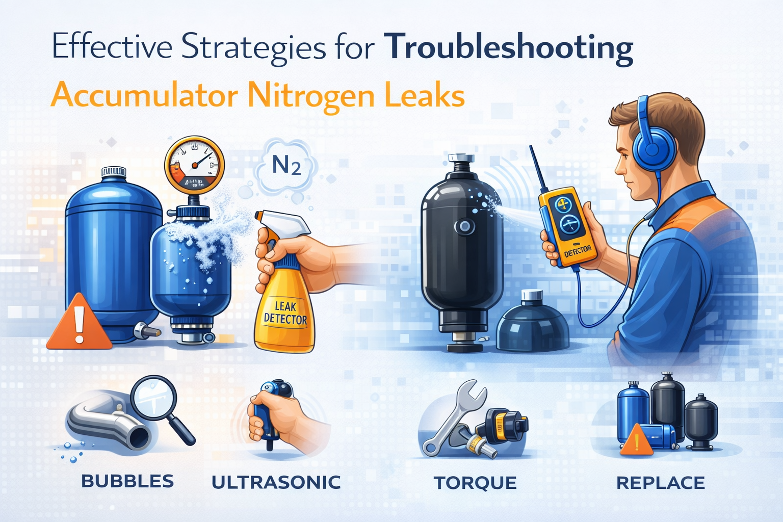
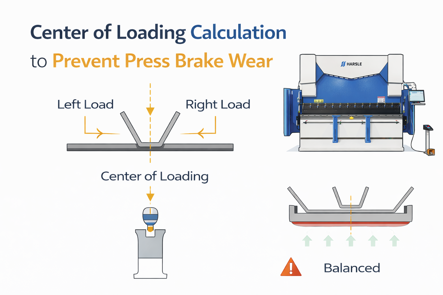
In Press Brake Operation, pressure sensors are integrated into the Y1 and Y2 axis control. If the sensor on the left cylinder fails, the ram will tilt, potentially damaging the guiding system. In Fiber Laser Cutting, nitrogen and oxygen pressures are monitored by high-speed sensors to ensure the piercing process is successful. A failure here results in ‘thermal runaway’ where the material melts uncontrollably. Finally, in Shearing Machines, pressure switches control the hold-down cylinders; if they fail to reach the set pressure, the machine will not allow the blade to descend, acting as a crucial safety interlock.
In the age of Industry 4.0, a smart pressure sensor doesn’t just fail; it provides diagnostic data that predicts its own end-of-life.
Conclusion and Recommendations
Troubleshooting pressure switch and sensor failures is a vital skill for maintaining the high-performance standards of modern sheet metal fabrication. By understanding the underlying physics of tonnage calculation, recognizing the signs of electrical interference, and following a disciplined diagnostic routine, maintenance teams can significantly reduce unplanned downtime. Always prioritize the use of high-quality, stainless-steel diaphragm sensors for hydraulic applications and ensure that your preventative maintenance schedule includes annual sensor calibration to guarantee the longevity and accuracy of your equipment.
Часто задаваемые вопросы
What is the most common cause of pressure sensor drift?
The most common causes are extreme temperature fluctuations and pressure spikes that exceed the proof pressure rating, leading to microscopic deformation of the internal diaphragm.
How do I know if my pressure switch is sticking?
If the system pressure drops significantly below the reset point but the switch fails to change state (continuity remains unchanged), the internal spring or piston is likely fouled by contaminated oil.
Can I replace a 0-10V sensor with a 4-20mA sensor?
Not directly. The PLC input card must be reconfigured or replaced, as 4-20mA is a current-loop signal and 0-10V is a voltage signal. 4-20mA is generally preferred in factories due to its higher resistance to electrical noise.
Why does my press brake show a ‘Pressure Timeout’ error?
This usually occurs when the PLC commands the pump to build pressure, but the pressure sensor doesn’t report the expected increase within a set timeframe. This could be a sensor failure, a stuck relief valve, or a major pump leak.
How often should industrial pressure sensors be calibrated?
For high-precision sheet metal work, such as aerospace or medical components, annual calibration is recommended. For general fabrication, bi-annual checks are usually sufficient unless accuracy issues are observed.