














Essential Features to Look for in a Deep Drawing Hydraulic Press

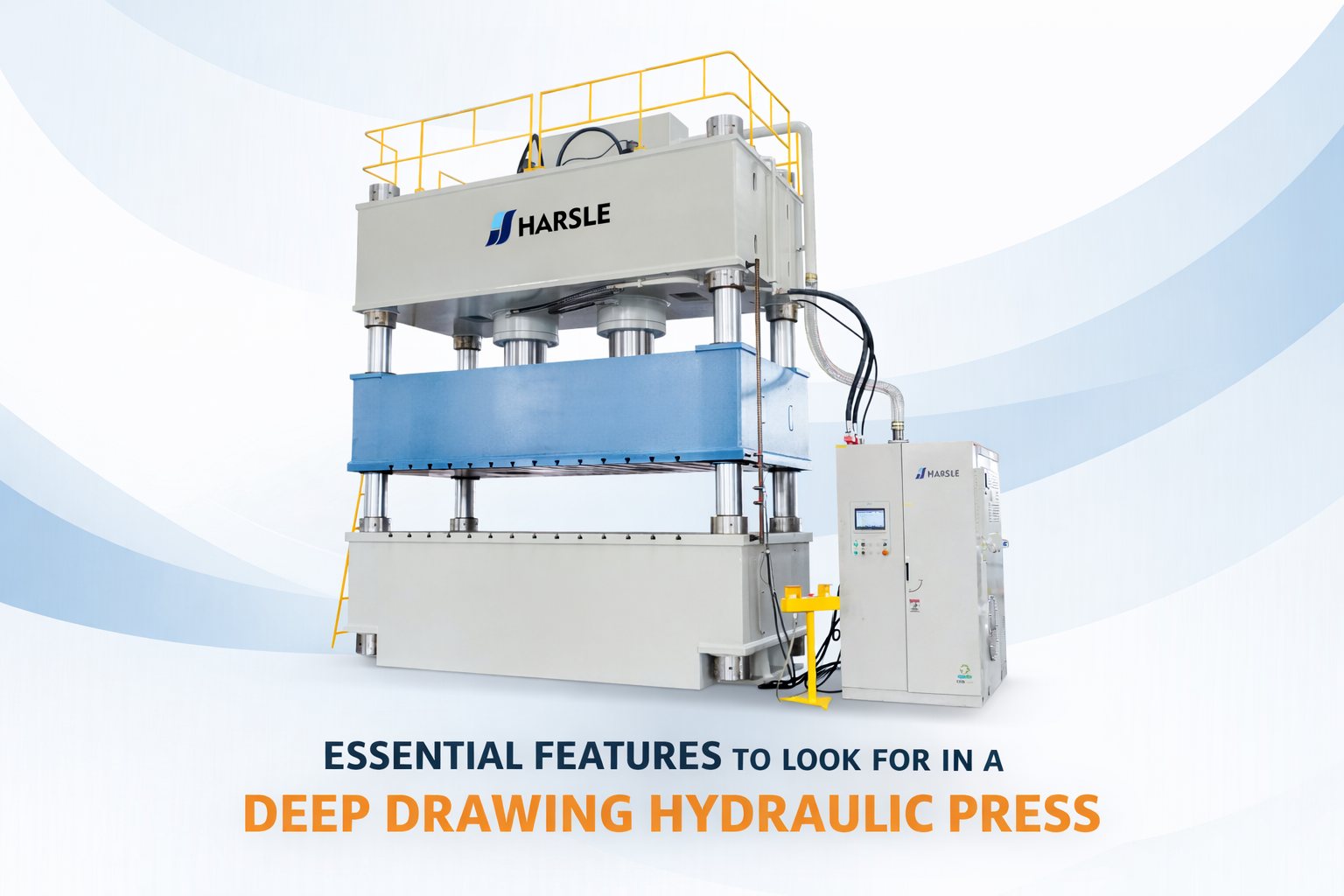
Deep drawing is one of the most versatile and complex metal-forming processes used in modern manufacturing, enabling the production of seamless, hollow, and complex-shaped parts from flat sheet metal. For any industrial facility, investing in a high-quality deep drawing hydraulic press is a strategic decision that impacts production speed, part quality, and long-term operational costs. These machines are engineered to handle extreme forces while maintaining the precise control required to transform flat blanks into deep vessels like automotive body parts, kitchen sinks, and industrial gas cylinders. Understanding the nuances of hydraulic control, frame engineering, and material behavior is essential for selecting a machine that meets the rigorous demands of high-precision forming. In this technical guide, we will analyze the fundamental features, engineering principles, and critical specifications that define a high-performance hydraulic press designed for deep drawing applications.
Understanding the Basics of a Deep Drawing Hydraulic Press
The core concept of a deep drawing hydraulic press involves a punch forcing a sheet metal blank into a die cavity. Unlike simple bending or stamping, deep drawing requires the material to undergo plastic deformation through a combination of tension and compression. A specialized hydraulic press for this task must manage two primary forces simultaneously: the punch force, which creates the shape, and the blank holder force, which prevents the material from wrinkling as it flows into the die. The hydraulic nature of the press is ideal for this process because it provides a constant force throughout the entire stroke, unlike mechanical presses where the force varies depending on the crankshaft position. This constant pressure is vital for maintaining the structural integrity of the metal, especially when working with high-strength alloys or thin-gauge materials where the margin for error is minimal.
Why the Deep Drawing Hydraulic Press Matters in Fabrication
In the realm of sheet metal fabrication, the ability to control material flow is the difference between a perfect part and a scrap piece. A deep drawing hydraulic press offers superior flexibility because the stroke length, pressure, and speed are fully adjustable. This allows engineers to fine-tune the process for different materials, such as aluminum, stainless steel, or titanium, each of which has unique hardening characteristics and drawing ratios. Furthermore, the hydraulic system allows for a “dwell” time at the bottom of the stroke, which is critical for setting the final shape and reducing springback. Without the precision of a modern hydraulic system, manufacturers would struggle with high rejection rates due to tearing, wrinkling, or inconsistent wall thickness, making the press the most critical asset in a deep drawing production line.
The success of a deep draw depends as much on the control of the metal flow as it does on the power of the press, requiring a delicate balance between punch velocity and blank holder pressure.
Key Factors to Look for in a Deep Drawing Hydraulic Press
When evaluating a machine, engineers must look beyond the maximum tonnage capacity. The following technical factors determine the versatility and reliability of the press:
- Frame Rigidity and Deflection: High-tonnage operations generate massive reactionary forces. An H-frame or four-column design is preferred for deep drawing to minimize deflection. Any frame misalignment during the stroke will lead to uneven wall thickness and premature tool wear.
- Hydraulic Cushion Technology: The hydraulic cushion (or blank holder) located in the bed of the press is vital. It must offer programmable, proportional pressure control to adapt to the changing resistance of the metal as it moves deeper into the die.
- Slide Guidance Systems: Precision-ground, multi-point gibbing systems ensure that the slide remains perfectly parallel to the bolster. This is critical for maintaining the clearance between the punch and die, which is often as tight as a few thousandths of an inch.
- Proportional Valve Control: Modern presses use electro-hydraulic proportional valves to control flow rates and pressures with millisecond responsiveness, allowing for complex speed profiles during a single stroke.
- Energy Efficiency: Look for servo-motor driven hydraulic pumps (Servo-Hydraulic systems) which significantly reduce energy consumption during idle times and offer quieter operation.
Technical Explanation and Drawing Force Calculation
Engineering a successful deep draw requires precise calculation of the required tonnage to ensure the press is not overloaded and the material does not fail. The primary force required is the punch force (Fp). The standard formula used by mechanical engineers is as follows:
Fp = pi * dm * t * Rm * K
Where:
- pi: Approximately 3.14159
- dm: Mean diameter of the finished cup (mm)
- t: Original blank thickness (mm)
- Rm: Ultimate tensile strength of the material (MPa or N/mm2)
- K: A correction factor that accounts for friction and the drawing ratio, typically ranging between 0.8 and 1.0.
In addition to the punch force, the blank holder force (Fh) must be calculated to prevent wrinkling. Generally, Fh is estimated as 30 percent to 40 percent of the punch force, though this depends heavily on the material type and the Limiting Drawing Ratio (LDR).
Common Material Drawing Coefficients
| Material Type | Tensile Strength (MPa) | Typical Max Draw Ratio | Lubrication Needs |
|---|---|---|---|
| Steel (Deep Draw Quality) | 280-350 | 2.0 – 2.2 | Medium (Oil-based) |
| Stainless Steel 304 | 515-600 | 1.8 – 2.0 | High (Chlorinated) |
| Aluminum 1100-O | 90-110 | 1.6 – 1.9 | Light (Synthetic) |
| Copper (Soft) | 200-250 | 2.1 – 2.2 | Medium |
Comparison of Press Configurations
Choosing the right architecture for your deep drawing hydraulic press depends on the part size and complexity. The table below compares the most common configurations used in industrial environments.
| Caratteristica | H-Frame (Straight-Side) | 4-Column Press | C-Frame (Gap) Press |
|---|---|---|---|
| Rigidity | Highest | High | Moderate |
| Access | Front and Back | 360 Degree Access | 3-Side Access |
| Tonnage Range | 500 – 5000+ Tons | 100 – 3000 Tons | 25 – 250 Tons |
| Precisione | Excellent | Buono | Fair (subject to yawning) |
| Best For | Heavy automotive body parts | Large, irregular components | Small, high-speed parts |
Step-by-Step Guide to Selecting a Press
1. Define Part Geometry: Determine the maximum depth of the draw and the diameter. This dictates the stroke length and the daylight (open height) of the press. Ensure the stroke is at least twice the depth of the part plus clearance for removal.
2. Calculate Total Tonnage: Use the formula provided above to find the punch force, then add the blank holder force and a 20 percent safety margin. This is your required press capacity.
3. Evaluate the Bed and Slide Area: The bolster size must accommodate the die set with enough room for clamping. Check that the press can handle off-center loading if you plan to run multi-stage or progressive dies.
4. Specify Control Requirements: For complex draws, specify a PLC with a HMI that allows for multiple pressure steps and speed changes throughout the stroke. Data logging is also essential for quality traceability.
5. Select Safety Features: Ensure the press complies with local safety standards (such as OSHA or CE). Look for dual-monitored hydraulic safety valves, light curtains, and redundant emergency stop circuits.
Common Mistakes to Avoid
One of the most frequent mistakes is underestimating the importance of the blank holder’s pressure profile. Many buyers opt for a static pressure cushion, only to find that the material tears because the pressure was too high at the start of the draw or wrinkles because it was too low at the end. Another common error is neglecting the frame’s deflection rate. In deep drawing, even a small amount of “yawning” or twisting in the frame can lead to asymmetrical parts and rapid tool degradation. Finally, ignoring the cooling system is a critical oversight. Deep drawing generates significant heat due to friction; if the hydraulic oil exceeds its optimal temperature (usually 50 degrees Celsius), the viscosity drops, leading to inconsistent speeds and potential damage to hydraulic components.
Industry Applications
The deep drawing hydraulic press is a staple in the Industria automobilistica, where it is used to form fuel tanks, oil pans, and door panels from high-strength steel. In the Aerospace Sector, these presses form lightweight aluminum and titanium alloy housings for engines and structural components. The Kitchenware and Appliance Industry relies on deep drawing for the mass production of stainless steel sinks, pots, and washing machine drums. Beyond these, the Medical Industry utilizes high-precision presses to form titanium implant shells and stainless steel surgical enclosures, where surface finish and dimensional accuracy are paramount.
Conclusione
Selecting the right deep drawing hydraulic press requires a deep understanding of the relationship between mechanical force, material science, and hydraulic control. By prioritizing frame rigidity, programmable cushion force, and advanced slide guidance, manufacturers can ensure a high ROI and superior part quality. As materials become stronger and more complex, the need for precision-engineered hydraulic systems will only grow. Engineers and plant managers must look at the press not just as a source of power, but as a sophisticated instrument of metal deformation that, when configured correctly, provides a significant competitive advantage in the global manufacturing landscape.
FAQ
What is the Limiting Drawing Ratio (LDR) in deep drawing?
The LDR is the ratio of the maximum blank diameter to the punch diameter that can be drawn without failure. It typically ranges from 1.6 to 2.2 depending on the material’s ductility and the press’s control capabilities.
Why is a hydraulic press preferred over a mechanical press for deep drawing?
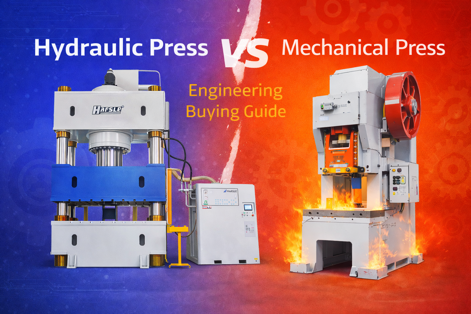
Hydraulic presses offer full tonnage at any point in the stroke and adjustable speeds, which are critical for controlling the plastic flow of metal. Mechanical presses have a fixed stroke and peak tonnage only at the bottom, making them less flexible for deep draws.
How does a hydraulic cushion assist in the drawing process?
The hydraulic cushion provides a controlled resistive force against the blank holder. This prevents the sheet metal from wrinkling as it is pulled into the die while allowing the material to slide at a controlled rate.
What maintenance is required for a deep drawing hydraulic press?
Regular maintenance includes monitoring oil cleanliness (ISO 4406 standards), checking for seal leaks, lubricating the slide gibs, and ensuring the nitrogen pre-charge in accumulators is at the correct level.
Can I use a single-action press for deep drawing?
Yes, a single-action press can perform deep drawing if it is equipped with a die cushion in the bed to act as a blank holder. Without a cushion or specialized tooling, a single-action press is limited to simple forming and stamping.