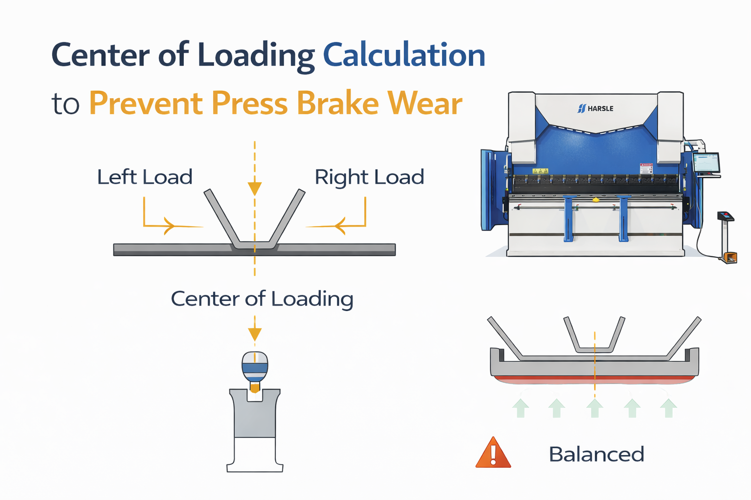
Center of Loading Calculation to Prevent Press Brake Wear
In the world of high-precision sheet metal fabrication, the longevity and accuracy of a press brake depend significantly on how force is distributed across the machine’s bed. The center of loading is a fundamental engineering concept that determines where the resultant force of a bending operation is concentrated. When the center of loading is misaligned with the machine’s drive cylinders, it creates eccentric loading—a primary cause of ram tilt, hydraulic seal failure, and uneven tool wear. For production managers and lead engineers, mastering the calculation of this point is not merely a matter of theoretical physics; it is a critical maintenance and quality control strategy that ensures consistent bending angles and protects significant capital investments.
Understanding the Basics of Center of Loading
The center of loading (COL) is the point along the longitudinal axis of the press brake ram where the sum of all bending forces is perfectly balanced. In a simple, single-bend operation where a part is centered on the machine, the COL typically aligns with the geometric center of the ram. However, in modern fabrication environments, complex multi-stage setups and off-center bending are common. These scenarios move the COL away from the machine’s centerline.
Press brakes are designed with hydraulic cylinders at either end of the ram. If the COL is closer to the left cylinder, that cylinder must exert more force than the right to maintain a parallel stroke. While modern CNC systems use linear encoders and proportional valves to compensate for this imbalance, there are physical limits to how much eccentric loading a machine can handle before the guide rails (gibbing) and hydraulic seals begin to suffer from excessive friction and heat.
The center of loading is the ‘gravity point’ of your mechanical force; ignore it, and the machine will eventually force you to pay for that oversight through downtime and structural wear.
Why the Center of Loading Matters in Sheet Metal Fabrication
Ignoring the center of loading leads to a cascade of mechanical issues that degrade both the machine and the final product. The most immediate impact is ‘ram tilt’ or ‘deflection error.’ Even with sophisticated crowning systems, an off-center load can cause the ram to twist slightly, leading to inconsistent flange angles across the length of the part. Over time, this imbalance causes uneven wear on the punches and dies, as the side closer to the load experiences higher localized pressure.
From a maintenance perspective, eccentric loading places a side-load on the hydraulic pistons. Hydraulic cylinders are designed for axial movement; lateral forces increase the wear on the ‘U-cups’ and ‘wear rings,’ leading to internal leaks and pressure loss. Furthermore, the gibbing—the precision tracks that guide the ram—can become scored or misaligned if they are constantly fighting an unbalanced load. Maintaining a balanced center of loading ensures that the machine operates within its design specifications, maximizing the lifespan of the hydraulic system and the accuracy of the backgauge.
Key Factors to Consider
When determining the center of loading, several variables must be evaluated simultaneously. It is not just about where the part sits, but how much force it requires relative to other tools in the setup.
- Material Thickness and Tensile Strength: Higher tonnage requirements pull the COL more aggressively toward that specific station.
- Bend Length: Longer bends distribute force over a wider area but can still shift the COL if placed asymmetrically.
- Tooling Selection: Different V-die openings change the required tonnage per millimeter of bend, directly affecting the force distribution.
- Machine Tonnage Capacity: Smaller machines have lower tolerances for eccentric loading compared to heavy-duty, large-format press brakes.
- Multi-Station Setups: When multiple sets of tools are mounted on the bed for sequential bending, the COL is the weighted average of all active stations.
Technical Explanation and Center of Loading Calculations
To calculate the center of loading, we must first determine the tonnage required for each individual bend in the setup. The standard formula for bending tonnage (T) in air bending is:
T = (L * t^2 * UTS) / (V * 1000)
Where:
L = Length of the bend (mm)
t = Material thickness (mm)
UTS = Ultimate Tensile Strength of the material (MPa or N/mm2)
V = V-die opening (mm)
Once the tonnage for each station is known, the Center of Loading (X_col) relative to a reference point (usually the left end of the ram) is calculated using the weighted average formula:
X_col = ( (T1 * x1) + (T2 * x2) + … + (Tn * xn) ) / (Total Tonnage)
In this formula, ‘Ti’ is the tonnage of an individual station, and ‘xi’ is the distance from the reference point to the center of that station. The resulting X_col value tells the operator exactly where the center of the combined load is located. Ideally, this point should be as close to the machine’s geometric centerline as possible.
| Material Type | Tensile Strength (MPa) | Tonnage Multiplier (Ref: Mild Steel) |
|---|---|---|
| Aluminum (5052-H32) | 230 | 0.50 |
| Mild Steel (A36) | 450 | 1.00 |
| Stainless Steel (304) | 600 | 1.40 |
| High-Strength Steel | 800+ | 1.80+ |
Comparison of Loading Methods
There are two primary ways to arrange tooling in a press brake: Central Loading and Distributed Loading. Understanding the trade-offs is essential for preventing off-center wear.
| Recurso | Central Loading | Distributed (Stage) Loading |
|---|---|---|
| Setup Complexity | Low – single station at center. | High – multiple tool sets. |
| Ram Wear | Minimal and symmetrical. | Potential for high eccentric wear. |
| Eficiência de produção | Lower – requires part handling. | Higher – complete part in one cycle. |
| Angle Accuracy | Most consistent. | Requires precise crowning adjustment. |
| Hydraulic Stress | Balanced pressure on both cylinders. | Differential pressure between cylinders. |
Steps to Calculate the Center of Loading for Stage Bending
Follow these steps to ensure your multi-station setup does not damage your press brake:
- Map the Tooling Layout: Measure the exact position of each die set along the bed, noting the center point of each tool relative to the left side of the machine.
- Calculate Individual Tonnages: Use the tonnage formula for each bend. Remember that different thicknesses or V-dies in the same setup will yield different tonnages.
- Determine the Total Tonnage: Sum the tonnages of all active stations that will be engaged simultaneously (if applicable) or consider the maximum force per stroke.
- Apply the Weighted Average Formula: Multiply each station’s tonnage by its position, sum them up, and divide by the total tonnage to find the COL.
- Adjust the Setup: If the calculated COL is more than 10-15% away from the machine centerline, shift the tooling layout to bring the COL closer to the middle.
Modern CNC controllers often have ‘Load Calculation’ modules, but understanding the manual math allows an engineer to verify the software and troubleshoot unexplained ram tilt.
Common Mistakes to Avoid
One of the most frequent errors is assuming that centering the workpiece on the dies is sufficient. If the dies themselves are offset to the left or right of the machine, the load is still eccentric. Another common mistake is ignoring the ‘blanking’ or ‘punching’ forces if using the press brake for specialized tasks; these forces are often more localized and can cause sudden spikes in off-center pressure.
Furthermore, operators often forget to account for the material’s grain direction. Bending against the grain requires more force than bending with the grain. If a stage setup involves parts with varying grain orientations, the tonnage distribution shifts, moving the center of loading away from its calculated geometric position.
Industry Applications
In the automotive sector, where structural components like B-pillars are bent using complex stage tooling, calculating the COL is vital for maintaining the strict tolerances required for robotized welding. Similarly, in the production of heavy-duty enclosures for the energy sector, using large-format press brakes to bend 12mm plate requires meticulous force balancing. Because these machines operate near their maximum tonnage limits, even a minor offset in the center of loading can result in permanent deformation of the ram or ‘crowning’ system failure.
Aerospace manufacturers also rely on these calculations when working with exotic alloys like Titanium or Inconel. Since these materials have extremely high tensile strengths, the forces involved are immense. Precise COL alignment ensures that the delicate surface finishes of aerospace components are not marred by the uneven tool contact caused by ram tilt.
Conclusão
Calculating the center of loading is an essential discipline for any fabrication shop aiming for high precision and machine longevity. By understanding how tonnage requirements and tool positioning interact, engineers can design setups that minimize eccentric loading and protect the press brake from off-center wear. Always prioritize balanced loading, use the weighted average formula for stage setups, and consult your machine’s manual for its specific eccentric loading limits. A balanced machine is a precise machine, and a precise machine is the foundation of a profitable fabrication business.
Perguntas frequentes
What is the maximum allowable offset for the center of loading?
Most manufacturers recommend keeping the center of loading within the middle 60% of the distance between the side frames. Exceeding this can lead to excessive ram tilt and hydraulic wear.
How does CNC crowning affect the center of loading?
Crowning compensates for bed deflection but does not correct for off-center loading. In fact, an off-center load makes the crowning system less effective because the deflection profile becomes asymmetrical.
Can I bend a small part at one end of a long press brake?
While possible, it is not recommended for high-tonnage jobs. If you must bend off-center, ensure the tonnage used is significantly below the machine’s maximum capacity to prevent twisting the ram.
Does the backgauge position affect the center of loading?
The backgauge affects part positioning but not the force calculation itself. However, if the backgauge is misaligned, it might force the operator to place the part off-center to achieve a square bend, indirectly shifting the COL.
Why do hydraulic seals leak more often on one side of my press brake?
This is a classic symptom of consistent off-center loading. The cylinder closest to the load works harder and experiences more lateral force, leading to faster seal degradation compared to the other side.