













Precision Straightening of Shafts and Plates Using Hydraulic Power


Precision straightening is a critical post-processing phase in metal fabrication and mechanical engineering, essential for restoring the dimensional integrity of shafts, plates, and structural profiles that have undergone deformation. During manufacturing processes such as heat treatment, welding, or heavy machining, internal residual stresses often cause components to warp or bend. Without precise correction, these deviations can lead to catastrophic failure in rotating machinery, excessive vibration, and poor assembly fitment.
The application of hydraulic power in this field provides the immense force and controllable stroke necessary to manipulate high-strength alloys. By leveraging hydraulic systems, engineers can apply targeted pressure to specific points of a workpiece, inducing plastic deformation to counteract unwanted curvature. This article delves into the technical nuances of precision straightening, the physics of material behavior under hydraulic force, and the best practices for achieving sub-millimeter tolerances in industrial environments.
Understanding the Basics of Hydraulic Straightening
At its core, precision straightening is the process of neutralizing unwanted curvature in a workpiece. This is achieved through the application of a bending moment that opposes the existing deformation. The process relies on the relationship between elastic and plastic deformation. When a shaft or plate is bent, it first undergoes elastic deformation; if the force is removed at this stage, the material returns to its original shape. To achieve a permanent change, the applied force must exceed the material’s yield strength, entering the plastic deformation zone.
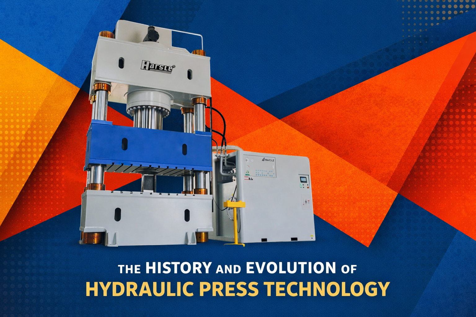
Hydraulic straightening presses utilize a hydraulic cylinder (ram) to apply force at a specific point, while the workpiece is supported at two or more points. Modern systems often incorporate sophisticated sensors and CNC controllers to monitor the deflection in real-time, ensuring that the ram stroke is precisely calculated to account for material springback—the tendency of the metal to partially return to its deformed state after the load is released.
Precision straightening is not merely about applying force; it is an exercise in controlled metallurgy, where the engineer must balance the material yield point against the required geometric correction without inducing structural fatigue.
Why Precision Straightening Matters in Sheet Metal Fabrication
In the context of sheet metal and heavy plate fabrication, flatness is often a contractual requirement. Plates used in laser cutting, for instance, must be perfectly flat to maintain a consistent focal point and prevent head collisions. Similarly, shafts used in drive systems must exhibit near-zero Total Indicator Reading (TIR) to avoid centrifugal imbalances at high RPMs.
Hydraulic straightening is preferred over mechanical or thermal methods because it offers superior repeatability and force density. While flame straightening relies on localized thermal expansion and contraction, which can alter the material’s grain structure and hardness, hydraulic straightening is a cold-working process that maintains the integrity of heat-treated surfaces. For large-scale industrial components, the ability to apply hundreds of tons of force with millimeter precision makes hydraulic power the industry standard.
Key Factors to Consider in the Straightening Process
Several technical variables dictate the success of a straightening operation. Engineers must evaluate these factors before initiating the hydraulic cycle:
- Material Yield Strength: Higher strength materials require significantly more force to reach the plastic deformation zone.
- Workpiece Geometry: The moment of inertia (I) of a circular shaft versus a rectangular plate fundamentally changes how the part responds to load.
- Support Span (L): The distance between the lower supports determines the bending moment. Increasing the span reduces the force required but increases the risk of local buckling.
- Initial Deflection: The magnitude of the bend determines whether the correction can be done in a single press or requires multiple incremental steps.
- Springback Ratio: This is the difference between the maximum deflection under load and the final position after unloading.
Technical Explanation and Force Calculations
To calculate the force required for straightening, we typically model the workpiece as a beam supported at two points with a concentrated load at the center. The goal is to reach the stress level where plastic deformation occurs at the outermost fibers of the material.
The simplified formula for the required force (F) in a three-point bending scenario is derived from the flexure formula:
F = (4 * Sigma * S) / L
Where:
- F: The force applied by the hydraulic ram (Newtons or Tons).
- Sigma (σ): The yield strength of the material (MPa or PSI).
- S: The section modulus of the workpiece (mm³ or in³). For a solid circular shaft, S = (π * d³) / 32. For a rectangular plate, S = (b * h²) / 6.
- L: The distance between the two bottom supports (mm or in).
For example, if an engineer is straightening a 100mm diameter steel shaft with a yield strength of 400 MPa using a support span of 1000mm, the section modulus (S) would be approximately 98,175 mm³. Substituting these values into the formula provides a baseline force requirement to initiate yielding, which is approximately 157,080 Newtons, or roughly 16 tons.
Comparison of Straightening Equipment Types
| Tính năng | Manual Hydraulic Press | Semi-Automatic Press | CNC Precision Straightening Machine |
|---|---|---|---|
| Control Accuracy | Low (Operator dependent) | Medium (Dial gauge assisted) | High (Laser sensor controlled) |
| Throughput | Slow | Moderate | Fast (High Volume) |
| Skill Requirement | High technical skill | Medium skill | Low (Programming required) |
| Primary Application | Repair shops, low volume | General fabrication | Automotive, Aerospace production |
| Cost | Low | Medium | High |
Step-by-Step Guide to the Straightening Process
- Measurement and Mapping: Place the workpiece on a set of rollers or V-blocks. Use a dial indicator or laser scanner to rotate the part and identify the point of maximum deflection (the high spot).
- Setup: Position the workpiece on the hydraulic press supports. Ensure the supports are placed symmetrically around the point of maximum deflection to ensure an even bending moment.
- Calculation of Stroke: Based on the material type and thickness, estimate the required ram travel. Remember that the total stroke must include the distance to close the gap, the distance for elastic deformation, and the distance for the necessary plastic correction.
- Initial Pressing: Apply hydraulic pressure gradually. Modern CNC machines will perform a “test press” to calculate the material’s specific springback constant.
- Verification: Release the pressure and re-measure the part. If the TIR is within the acceptable tolerance (e.g., < 0.05mm), the process is complete. If not, repeat the steps with adjusted force.
- Stress Relieving (Optional): For critical components, a low-temperature stress-relief heat treatment may follow to stabilize the corrected geometry.
A common misconception is that more force leads to faster results. In reality, precision is found in the ‘over-bend’ calculation—successfully predicting exactly how much the material will spring back after the ram retracts.
Common Mistakes to Avoid
In the pursuit of precision, even experienced operators can encounter pitfalls that compromise the integrity of the workpiece:
- Ignoring Support Placement: Placing supports too close together requires excessive force, which can cause surface indentation or “bruising” on the shaft.
- Over-Correction: Applying too much force can create a bend in the opposite direction. Repeatedly bending a part back and forth leads to work hardening and increases the risk of brittle fracture.
- Neglecting Surface Protection: For chrome-plated or ground shafts, using hardened steel V-blocks without brass or aluminum shims can ruin the surface finish.
- Failure to Account for Temperature: Straightening a part that is still hot from welding or machining will result in dimensional shifts as it cools to room temperature.
Industry Applications of Precision Hydraulic Straightening
The versatility of hydraulic power makes it indispensable across various sectors:
Automotive and Drivetrain
Drive shafts, axle housings, and crankshafts must be perfectly straight to ensure smooth power transmission. Automated hydraulic straightening cells are integrated into production lines to correct distortions caused by induction hardening.
Aerospace Components
Structural landing gear components and long fuselage stringers require extreme precision. Because these parts are often made from high-strength titanium or aluminum alloys, hydraulic presses with fine-tuned proportional valves are used to prevent cracking.
Construction and Heavy Plate
In the production of wear plates for mining or large structural baseplates for machinery, hydraulic leveling machines use a series of rollers and hydraulic rams to ensure flatness over several meters of material.
Conclusion: The Future of Hydraulic Straightening
Precision straightening remains a cornerstone of high-quality mechanical manufacturing. While the fundamental physics of hydraulic power remain the same, the integration of Industry 4.0 technologies—such as laser measurement, AI-driven springback prediction, and real-time data logging—has transformed it from a manual craft into a high-tech science. For factory owners and engineers, investing in modern hydraulic straightening equipment translates to lower scrap rates, higher product reliability, and a significant competitive advantage in precision-demanding markets. As materials science evolves with harder and more complex alloys, the controllability and power of hydraulic systems will continue to be the preferred solution for dimensional correction.
Câu hỏi thường gặp
What is springback in hydraulic straightening?
Springback is the elastic recovery of a material after the hydraulic force is released. To achieve a final straight shape, the operator must over-bend the part slightly into the plastic zone so that it returns to the desired position after rebounding.
Can all materials be straightened using hydraulic power?
Most ductile metals like carbon steel, stainless steel, aluminum, and copper can be straightened. However, extremely brittle materials like certain cast irons or hardened tool steels may crack rather than bend when subjected to straightening forces.
How does support span distance affect the straightening force?
The force required is inversely proportional to the support span. Increasing the distance between the bottom supports increases the leverage (bending moment), thereby reducing the hydraulic tonnage needed to achieve yielding.
What is TIR and why is it important?
Total Indicator Reading (TIR) is the total variation in the surface of a rotating part measured by a dial indicator. In straightening, TIR is the primary metric used to determine if a shaft is within the required concentricity and straightness tolerances.
Is cold straightening better than flame straightening?
Hydraulic cold straightening is generally preferred for precision components because it does not alter the metallurgical properties or surface finish of the material, whereas flame straightening can cause localized softening or stress concentrations.