













Understanding PSI and Total Force in Hydraulic Press Brakes

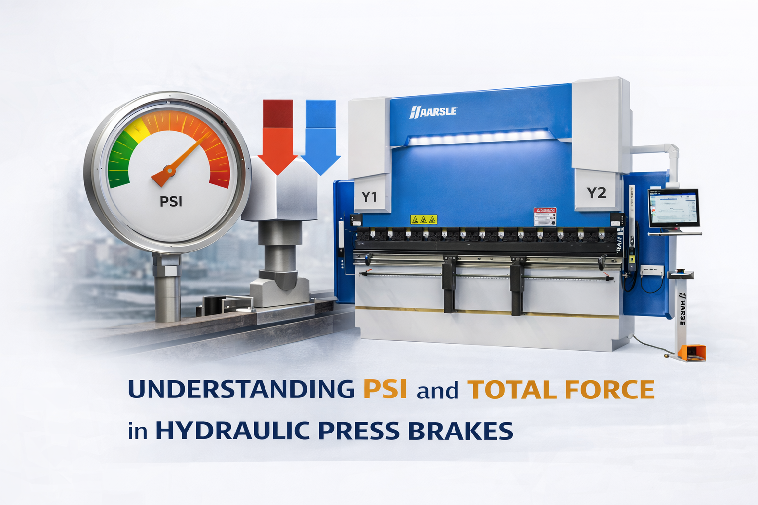
In the world of sheet metal fabrication, precision is the byproduct of controlled power. For engineers and workshop managers operating hydraulic machinery like press brakes, shearing machines, and rolling mills, the distinction between hydraulic pressure and the resulting mechanical force is fundamental. Understanding the relationship between PSI and total force is not merely an academic exercise; it is a critical operational requirement for ensuring material integrity, machine longevity, and operator safety. When we speak of a 100-ton press brake, that ‘100 tons’ is the total force generated at the ram, but the engine driving that force is the hydraulic pressure measured in pounds per square inch (PSI).
This article provides a deep dive into the mechanical engineering principles that govern hydraulic systems in metalworking. We will explore how energy is transferred from a pump to a cylinder and ultimately to the workpiece. By the end of this technical guide, you will have a thorough grasp of how to calculate tonnage from pressure, why cylinder surface area is the most important variable in the equation, and how to optimize your hydraulic systems for peak performance in heavy-duty fabrication environments.
Understanding the Basics: Pressure vs. Force
To understand the relationship between PSI and total force, we must first define the two terms within the context of fluid mechanics. PSI (Pounds per Square Inch) is a measurement of pressure, representing the amount of force exerted by a fluid on a specific unit of area. In a hydraulic system, the pump creates flow, and the resistance to that flow creates pressure. Total Force, often expressed in tons in the United States or kilonewtons (kN) in metric systems, is the cumulative load exerted by the hydraulic cylinder’s piston onto the tooling and the workpiece.
The bridge between these two concepts is Pascal’s Law, which states that pressure applied to a confined fluid is transmitted undiminished in every direction throughout the fluid and acts with equal force on equal areas. In a press brake cylinder, this means the pressure generated by the hydraulic unit acts uniformly across the surface of the piston. However, the total force output depends entirely on the size of that piston. A high-pressure system with a small cylinder might produce less force than a low-pressure system with a massive cylinder.
Why This Topic Matters in Sheet Metal Fabrication
In modern manufacturing, accuracy is measured in microns and seconds. Miscalculating the relationship between PSI and total force can lead to several catastrophic or costly outcomes. First, there is the risk of machine overloading. If an operator assumes that increasing the relief valve pressure will safely provide more bending power without accounting for the structural limits of the frame, the machine may suffer from permanent deformation or ‘ram upset.’
Secondly, tooling protection is paramount. Every die and punch has a maximum load rating (tons per foot). Exerting excessive force due to a misunderstanding of hydraulic output can cause hardened tool steel to shatter, posing a significant safety risk. Finally, for consistent bending angles, the machine must deliver repeatable force. Fluctuations in pressure or a lack of understanding of the pressure-to-force ratio will result in inconsistent springback and rejected parts, especially when working with high-strength materials like stainless steel or HARDOX.
The hydraulic system is the heart of the press brake, but the cylinder area is its mechanical advantage. Without calculating the effective surface area, a pressure gauge reading is just an arbitrary number.
Key Factors to Consider in Force Calculation
When analyzing the force output of sheet metal equipment, several technical variables must be factored into the engineering equation:
- Cylinder Bore Diameter: This is the internal diameter of the hydraulic cylinder. The larger the bore, the more surface area the pressurized fluid has to push against.
- Effective Piston Area: This is the calculated area of the piston head. In double-acting cylinders, the ‘extend’ side area is larger than the ‘retract’ side area because the piston rod occupies space on the return side.
- System Efficiency: No hydraulic system is 100 percent efficient. Friction between seals and cylinder walls, as well as pressure drops across valves and hoses, typically results in a 5% to 10% loss of theoretical force.
- Material Yield Strength: The amount of force required is dictated by the material’s resistance to deformation. Knowing the total force available at a specific PSI allows you to determine if a machine can handle specific thicknesses of high-tensile alloys.
Technical Explanation and Engineering Formulas
The relationship between pressure and force is mathematically linear. The fundamental formula used by mechanical engineers to determine the output of a hydraulic cylinder is:
Force = Pressure × Area
Where:
- Force (F): Measured in pounds (lbs).
- Pressure (P): Measured in Pounds per Square Inch (PSI).
- Area (A): The effective surface area of the piston in square inches (sq. in.).
To convert the resulting force into the industry-standard ‘Tonnage,’ use the following conversion:
Tons = Force (lbs) / 2,000
Engineering Example:
Consider a press brake with two hydraulic cylinders, each having a bore diameter of 6 inches. The system is running at a maximum pressure of 3,000 PSI. Let’s calculate the total tonnage of the machine.
1. Calculate the radius of the cylinder: 6 inches / 2 = 3 inches.
2. Calculate the Area (A = πr²): 3.14159 × 3² = 28.27 square inches per cylinder.
3. Total Area for both cylinders: 28.27 × 2 = 56.54 square inches.
4. Calculate Total Force: 3,000 PSI × 56.54 sq. in. = 169,620 lbs.
5. Convert to Tonnage: 169,620 / 2,000 = 84.81 Tons.
Theoretical Force Output Table (Per Cylinder)
The following table illustrates how varying the cylinder bore diameter significantly impacts the total force at a constant pressure of 2,500 PSI.
| Bore Diameter (Inches) | Piston Area (Sq. In.) | Force at 2,500 PSI (Lbs) | Tonnage (Tons) |
|---|---|---|---|
| 3.0 | 7.07 | 17,675 | 8.8 |
| 4.0 | 12.57 | 31,425 | 15.7 |
| 5.0 | 19.63 | 49,075 | 24.5 |
| 6.0 | 28.27 | 70,675 | 35.3 |
| 8.0 | 50.27 | 125,675 | 62.8 |
Comparison: Hydraulic vs. Mechanical Force Delivery
While this article focuses on the PSI-to-force relationship in hydraulic systems, it is important to contrast this with mechanical systems to understand why hydraulic control is often preferred in modern fabrication.
| Recurso | Hydraulic Systems (PSI Based) | Mechanical Systems (Flywheel Based) |
|---|---|---|
| Force Consistency | Constant force throughout the entire stroke. | Force varies based on the position of the stroke (max at bottom). |
| Overload Protection | Pressure relief valves prevent exceeding limits. | Difficult to protect; shear pins or clutches are required. |
| Adjustability | Force can be easily adjusted by changing PSI. | Force is fixed based on machine design and speed. |
| Stroke Control | Variable and highly precise. | Fixed by the eccentricity of the crankshaft. |
Step-by-Step Guide: Calculating Required PSI for a Job
If you are a shop floor manager and you need to ensure your machine has enough power for a specific bend, follow these steps:
- Determine Required Tonnage: Use a standard air-bending chart to find the tons per foot required for your material thickness, tensile strength, and V-die opening.
- Calculate Total Required Force: Multiply the tons per foot by the length of the part (in feet).
- Identify Cylinder Area: Consult your machine’s technical manual to find the total effective piston area (sum of all main cylinders).
- Calculate Necessary PSI: Divide the total required force (in lbs) by the total piston area.
- Safety Check: Ensure the calculated PSI is at least 10-15% below the machine’s maximum rated pressure to account for efficiency losses and avoid straining the hydraulic pump.
Common Mistakes to Avoid
Engineers and operators often fall into traps when dealing with hydraulic force calculations. One common error is ignoring the rod displacement. When calculating the retraction force (important for heavy top tools), you must subtract the area of the piston rod from the bore area. Failing to do this can lead to the machine being unable to lift heavy custom punches.
Another frequent mistake is assuming linear pressure scaling across different machines. Just because a 100-ton machine runs at 3,000 PSI does not mean every 100-ton machine does. A manufacturer might use larger cylinders and lower pressure to reduce seal wear, or smaller cylinders and higher pressure to achieve faster cycle times. Always verify the cylinder bore diameter before making assumptions about the PSI/Force ratio.
In hydraulic engineering, pressure is the ‘how hard’ and area is the ‘how much.’ If you increase the ‘how hard’ without checking the machine’s structural integrity, the ‘how much’ will eventually break the frame.
Industry Applications
The relationship between PSI and force is applied across various sectors. In the aerospace industry, where exotic alloys like Titanium are common, precise PSI control is used to prevent micro-fractures during the forming process. In heavy plate fabrication for shipbuilding or construction, massive cylinders are used to convert moderate PSI into thousands of tons of force to bend 2-inch thick steel plates.
In automated panel bending, sophisticated CNC systems modulate hydraulic pressure in real-time. By monitoring the PSI needed to achieve a certain degree of deformation, the machine can actually ‘sense’ the material’s yield strength and adjust the stroke depth automatically to compensate for springback variations between batches of steel.
Conclusão
The relationship between PSI and total force is the cornerstone of hydraulic machine operation in the sheet metal industry. By understanding that Force = Pressure × Area, engineers can maximize the capabilities of their equipment while maintaining a strict safety margin. Whether you are sizing a new press brake purchase or troubleshooting a forming issue on the shop floor, always return to the fundamentals: check your cylinder areas, monitor your pressure gauges, and ensure your calculations account for system efficiencies. Mastery of these variables leads to more precise parts, safer work environments, and a more profitable fabrication operation.
Perguntas frequentes
How do I find the effective piston area of my press brake?
The effective area is usually listed in the machine’s technical specifications manual. If not available, you can calculate it by measuring the internal bore diameter of the cylinder and using the formula Area = 3.14159 x (Radius squared).
Does increasing the PSI always increase the bending force?
Yes, force is directly proportional to pressure. However, you must never exceed the manufacturer’s maximum PSI rating, as this can cause structural failure of the machine frame or blow out hydraulic seals.
Why does my pressure gauge show high PSI but the machine lacks power?
This usually indicates internal bypass leakage. Fluid may be leaking past the piston seals or through a faulty directional valve, meaning the pressure is being measured but the fluid isn’t effectively pushing against the piston to create force.
Is there a difference between PSI and Bar in these calculations?
They are both units of pressure. 1 Bar is approximately 14.5 PSI. If your machine uses Bar, simply convert it to PSI before using the standard force formula, or use the metric formula: Force (Newtons) = Pressure (Pascals) x Area (Square Meters).
How much force is lost to friction in a typical hydraulic cylinder?
In a well-maintained system, friction losses typically range from 3% to 7%. This is caused by the resistance of the U-cup seals and wiper seals against the cylinder wall.